Thursday, 28 June 2012

Transmissin and Drivelines

                                                   CLUTCH

A clutch is two metal plates in the engine. When you press the clutch pedal down the plates come apart separating the engine from the drive wheels allowing you to change gear. Bringing the pedal back up re-engages the plates which in turn connect the engine to the drive wheels. As your car engine is constantly running, a clutch is needed to separate the engine from the drive wheels when you stop the car. Pressing the clutch down just before you stop does just this, otherwise the car would stall.


GEARBOX

Front Wheel gearbox


Rear Wheel gearbox 


Automatic Gearbox


Transaxle Gearbox

In the automotive field, a transaxle is a major mechanical component that combines the functionality of the transmission, the differential, and associated components of the driven axle into one integrated assembly.

Synchroniser: it is a toothed ring between the gears of a manual transmission that helps bring the 2 sets of gears to the same speed so they mesh easily during a shift.
Circlip: A circlip (a combination of 'circle' and 'clip', and pronounced thus), also known as a C-Clip, snap ring or Jesus clip, is a type of fastener consisting of a semi-flexible metal ring with open ends which can be snapped into place, into a machined groove on a dowel pin or other part to permit rotation but to prevent lateral movement. There are two basic types: internal and external, referring to whether they are fitted into a bore or over a shaft. Circlips are often used to secure pinned connections.
Bell housing: is a colloquial/slang term for the portion of the transmission that covers the flywheel and the clutch or torque converter of the transmission on vehicles powered by internal combustion engines.
Torque converter: The torque converter normally takes the place of a mechanical clutch in a vehicle with an automatic transmission, allowing the load to be separated from the power source. It is usually located between the engine's flex plate and the transmission.

Wednesday, 27 June 2012

Fuel and Fuel system


                                   Fuel and fuel system
INJECTORS


To test your injectors, you have different ways, u can use noid light, multi meter or use a screw driver to hear the injectors moving or spraying.
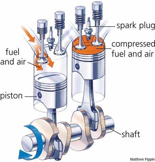
The primary difference between carburetors and fuel injection is that fuel injection atomizes the fuel by forcibly pumping it through a small nozzle under high pressure, while a carburetor relies on suction created by intake air rushing through to draw the fuel into the airstream.
Reflection
When using the Noid light, you need to disconnect the sensor wire and plug the noid light in, if it keeps flashing then its defiantly working. And need to check the sensor wire, it should be around 5v. Injectors also need to spray equally, if its blocked up then you need to replace it.
Testing Emissions

Catalytic converter

The catalytic converter is a device placed in the exhaust pipe, which converts hydrocarbons, carbon monoxide, and NOx into less harmful gases by using a combination of platinum, palladium and rhodium as catalyst.


Exhaust Gas Recirculation
Exhaust neither burns nor supports combustion, so it dilutes the air/fuel charge to reduce peak combustion chamber temperatures. This, in turn, reduces the formation of Nitro oxide
Fuel Pump
A fuel pump is a frequently (but not always) essential component on a car or other internal combustion engine device. Many engines (older motorcycle engines in particular) do not require any fuel pump at all, requiring only gravity to feed fuel from the fuel tank through a line or hose to the engine. But in non-gravity feed designs, fuel has to be pumped from the fuel tank to the engine and delivered under low pressure to the carburetor or under high pressure to the fuel injection system. Often, carbureted engines use low pressure mechanical pumps that are mounted outside the fuel tank, whereas fuel injected engines often use electric fuel pumps that are mounted inside the fuel tank (and some fuel injected engines have two fuel pumps: one low pressure/high volume supply pump in the tank and one high pressure/low volume pump on or near the engine).
Diesel Glow Plug
Glow plugs can be tested by, taking the glow plug out and putting 12volts on it. And if it is working well it should get bright red within 10 seconds.
The engine is unable to start, because it cannot generate and maintain enough heat for the fuel to ignite. For that reason indirect injected diesel engines are manufactured with glow-plugs in each pre chamber, and direct injected diesel engines are manufactured with glow-plugs in each combustion chamber to heat up the air.
Fuel Pressure regulator
SENSORS
Map:  The manifold absolute pressure sensor (MAP sensor) is one of the sensors used in an internal combustion engines electronic control system. Engines that use a MAP sensor are typically fuel injected. The manifold absolute pressure sensor provides instantaneous manifold pressure information to the engine's electronic control unit (ECU).
Maf: A mass air flow sensor is used to find out the mass flow rate of air entering a fuel-injected internal combustion engine. The air mass information is necessary for the engine control unit (ECU) to balance and deliver the correct fuel mass to the engine
Tps: A throttle position sensor (TPS) is a sensor used to monitor the position of the throttle in an internal combustion engine. The sensor is usually located on the butterfly spindle so that it can directly monitor the position of the throttle
Bleeding Diesel Engine

Here are the steps to take in bleeding air from a diesel fuel system:
1. Turn off fuel valve.
2. Clean outside of filter housing.
3. Install new filter element and new gaskets. A little oil on the gasket will aid a tight
seal.
4. I'd suggest that you fill a spin-on filter with clean fuel before installation.
5. Open the bleed plug on the filter closest to the fuel tank.
6. Open fuel supply valve so that the fuel is available to the filter and pump.
7. Most all equipment has a hand priming pump lever to pump fuel through the system
and replace trapped air. (Check operator's manual.) Pump several times until full
flow, without air bubbles, escapes from the bleed plug holes.
8. You may need to bleed filters, fuel pump and lines to the injectors.
9. Close bleed plugs after all air is removed from the fuel tank, filters, settlement bulb,
and fuel pump (only one at a time working through all bleed screws beginning closest
to tank and ending at nozzles if necessary).
10. Try the engine; if it doesn't start or runs poorly, you may have to bleed the injection
line.
11. Loosen injection lines at the injectors about one turn. The use of two wrenches will
prevent the binding or twisting of the steel lines. Usually, it is enough to bleed just half
of the lines at a time.
12. Crank the engine until all air is forced out and fuel is present.
13. Engine will start to pop on one or two cylinders.
14. Tighten the injector lock nut one at a time to tell by sound which cylinders are firing
properly.
15. Run the engine until it runs smoothly. This will bleed the other injectors.

Saturday, 26 May 2012

Valve Clearance


Valve clearance is the distance or gap between the cam and the top of the valve.  Because the engine has a rocker arm between the cam and valve, we measure this clearance as the distance between the cam and the rocker arm pad. We adjust the clearance by turning a set screw located at the end of the rocker arm.  The bottom of this screw effectively rests on top of the valve, so turning the screw clockwise moves the rocker arm up towards the cam (less clearance), and falls away (more clearance) if we turn the screw counter clockwise.We need to occasionally check and adjust valve clearance because the these components wear slightly with use and the clearance may fall out of the specified range resulting in extra wear (not enough clearance) or lost performance and noisy engine (too much clearance). 


cylinder block


         PISTONS


This picture shows the basic function of the pistons. Basically when the air and fuel mixture is compressed
it ignites and creates a spark for the spark plug. the crank shaft makes the pistons move up and down and also in a order.

CRANKSHAFT


 Receives oscillating motion from connecting rod and gives a rotary motion to the main shaft.It also drives the camshaft which actuate the valves of the engine.


 Cam Shaft
It takes driving force from crankshaft through gear train or chain and operates the inlet valve as well as exhaust valve with the help of cam followers, push rod and rocker arms.

Inlet Valve & Exhaust Valve
Inlet valve allow the fresh charge of air-fuel mixture to enter the cylinder bore. Exhaust valve permits the burnt gases to escape from the cylinder bore at proper timing.

Carburettor
It converts petrol in fine spray and mixes with air in proper ratio as per requirement of the engine.


Oil pump


The oil pump in an internal combustion engine circulates engine oil under pressure to the rotating bearings, the sliding pistons and the camshaft of the engine. This lubricates the bearings, allows the use of higher-capacity fluid bearings and also assists in cooling the engine.
The oil pressure generated in most engines should be about 10 psi per every 1000 revolutions per minute (rpm)
The oil pressure at the pump outlet, which is what opens the pressure relief valve, is simply the resistance to flow caused by the bearing clearances and restrictions.

Monday, 2 April 2012

Engines

Cylinder head

THEORY BACKGROUND 
The cylinder head sits on top of the cylinder.
It is where compression, spark and combustion take place.
It also holds the Valves and spark plug
Valves open and close to allow the air fuel mixture into the cylinder and the exhaust
fumes out of the cylinder.

Experiment

We used a precision straight edge and feeler gauge, to measure the head face surface for warpage.
We used the straight edge in six different direction and checked what feeler gauge fits in and 
also used light to see how big the gap was. If the gap is too big than its no good because of the 
leakage it can cause. 

Also carried measuring the valve stems to see if they are worn, I used a micro meter for this.

Reflection


Today I learned what a straight edge is and how it can be used with feeler gauge
I also learned that the cylinder head is made from Aluminum.
Taking the Valves out was a mission and a half, it took forever because we had a 16 valve 
engine, but I learned how to take them out properly and how to measure the stem.


   Whats in the cylinder


Wednesday, 28 March 2012

Fuel system

Theory and background


The fuel pump, pumps the fuel through the feed line which goes through the fuel filter which then
goes to the fuel rail, which the injectors are connected to. The fuel pressure is controlled by fuel pressure
regulator. So when you drive the car at high revs there isn't enough vacuum in the manifold to open the valves which allows the fuel in the return line.

Procedure for experiment
Resistance test. Remove the harness connector from every injector. Using an ohmmeter we tested the resistance by using the injector terminals.
Checking injectors electrical signal by using noid light, and if the light goes brighter when you rev the car, then its good.
Checking injector operation by engine speed  while the engine is running i disconnected one injector plug at a time and recorded the RPM drop which gave me the Average of 100rpm
Checking injector winding resistance  With the engine turned off by using the ohm meter and checked the resistance of each injector winding, and the results was average of 14.5 ohms.

 Reflection on experiment
The overall results that I got was good because the noid light showed that the injectors had low resistance
when the car was reved  up.
When Checking the winding resistance the Normal spec reading should be around 16ohms according to the video below :)