Valve clearance is the distance or gap between the cam and the top of
the valve. Because the engine has a rocker arm between the cam and valve,
we measure this clearance as the distance between the cam and the rocker arm
pad. We adjust the clearance by turning a set screw located at the end of
the rocker arm. The bottom of this screw effectively rests on top of the
valve, so turning the screw clockwise moves the rocker arm up towards the cam
(less clearance), and falls away (more clearance) if we turn the screw counter
clockwise.We need to occasionally check and adjust valve
clearance because the these components wear slightly with use and the clearance
may fall out of the specified range resulting in extra wear (not enough
clearance) or lost performance and noisy engine (too much clearance).
Saturday, 26 May 2012

cylinder block
PISTONS
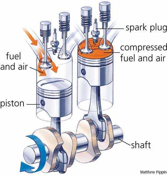
This picture shows the basic function of the pistons. Basically when the air and fuel mixture is compressed
it ignites and creates a spark for the spark plug. the crank shaft makes the pistons move up and down and also in a order.
CRANKSHAFT
Cam Shaft
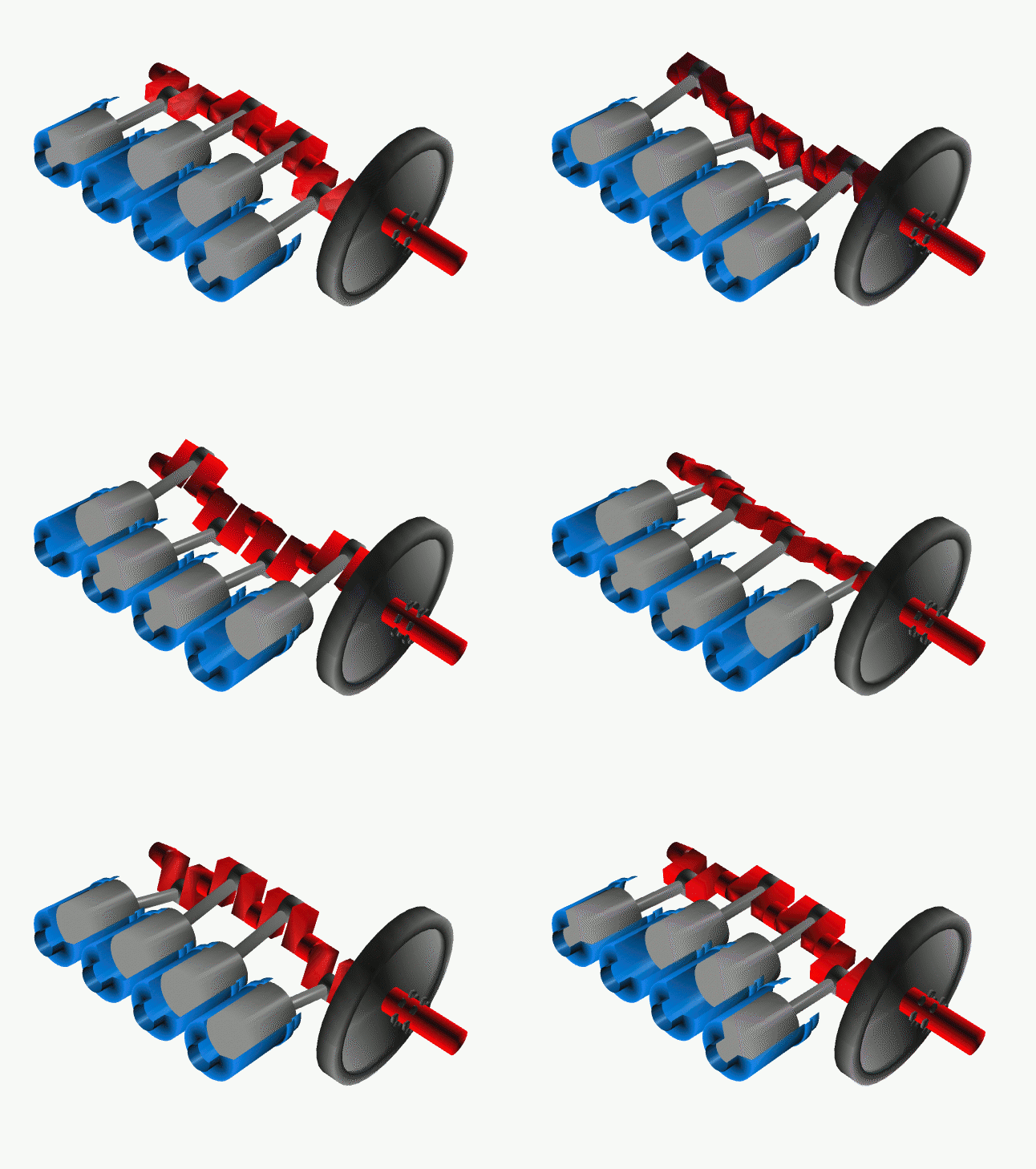
It takes driving
force from crankshaft through gear train or chain and operates the inlet valve as
well as exhaust valve with the help of cam followers, push rod and rocker arms.
Inlet Valve & Exhaust
Valve
Inlet valve allow the
fresh charge of air-fuel mixture to enter the
cylinder bore. Exhaust valve permits the burnt gases to
escape from the cylinder bore at proper timing.
Carburettor
It
converts petrol in fine spray and
mixes with air in proper ratio as per requirement of the engine.
Oil pump
The oil pump in an internal
combustion engine circulates engine oil under pressure
to the rotating bearings, the sliding pistons and the camshaft of the engine.
This lubricates the bearings, allows the use of higher-capacity fluid bearings and also assists in cooling the
engine.
The oil pressure generated in most engines should
be about 10 psi per every 1000 revolutions per minute (rpm)
The oil pressure at the pump outlet, which is
what opens the pressure relief valve, is simply the resistance to flow caused
by the bearing clearances and restrictions.

Monday, 2 April 2012
Engines
Cylinder head
THEORY BACKGROUNDThe cylinder head sits on top of the cylinder.
It is where compression, spark and combustion take place.
It also holds the Valves and spark plug
Valves open and close to allow the air fuel mixture into the cylinder and the exhaust
fumes out of the cylinder.
Experiment
We used a precision straight edge and feeler gauge, to measure the head face surface for warpage.
We used the straight edge in six different direction and checked what feeler gauge fits in and
also used light to see how big the gap was. If the gap is too big than its no good because of the
leakage it can cause.
Also carried measuring the valve stems to see if they are worn, I used a micro meter for this.
Reflection
Today I learned what a straight edge is and how it can be used with feeler gauge
I also learned that the cylinder head is made from Aluminum.
Taking the Valves out was a mission and a half, it took forever because we had a 16 valve
engine, but I learned how to take them out properly and how to measure the stem.

Whats in the cylinder


Wednesday, 28 March 2012
Fuel system
Theory and background

The fuel pump, pumps the fuel through the feed line which goes through the fuel filter which then
goes to the fuel rail, which the injectors are connected to. The fuel pressure is controlled by fuel pressure
regulator. So when you drive the car at high revs there isn't enough vacuum in the manifold to open the valves which allows the fuel in the return line.
Procedure for experiment
Resistance test. Remove the harness connector from every injector. Using an ohmmeter we tested the resistance by using the injector terminals.
Checking injectors electrical signal by using noid light, and if the light goes brighter when you rev the car, then its good.
Checking injector operation by engine speed while the engine is running i disconnected one injector plug at a time and recorded the RPM drop which gave me the Average of 100rpm
Checking injector winding resistance With the engine turned off by using the ohm meter and checked the resistance of each injector winding, and the results was average of 14.5 ohms.
Reflection on experiment
The overall results that I got was good because the noid light showed that the injectors had low resistance
when the car was reved up.
When Checking the winding resistance the Normal spec reading should be around 16ohms according to the video below :)

The fuel pump, pumps the fuel through the feed line which goes through the fuel filter which then
goes to the fuel rail, which the injectors are connected to. The fuel pressure is controlled by fuel pressure
regulator. So when you drive the car at high revs there isn't enough vacuum in the manifold to open the valves which allows the fuel in the return line.
Procedure for experiment
Resistance test. Remove the harness connector from every injector. Using an ohmmeter we tested the resistance by using the injector terminals.
Checking injectors electrical signal by using noid light, and if the light goes brighter when you rev the car, then its good.
Checking injector operation by engine speed while the engine is running i disconnected one injector plug at a time and recorded the RPM drop which gave me the Average of 100rpm
Checking injector winding resistance With the engine turned off by using the ohm meter and checked the resistance of each injector winding, and the results was average of 14.5 ohms.
Reflection on experiment
The overall results that I got was good because the noid light showed that the injectors had low resistance
when the car was reved up.
When Checking the winding resistance the Normal spec reading should be around 16ohms according to the video below :)
Wednesday, 14 March 2012
Starter motor

- Main Housing (yoke)
- Overrunning clutch
- Armature
- Field coils
- Brushes
- Solenoid
When the start switch is closed, the coils in the solenoid are
energized, creating a magnetic field. The field pulls the plunger
inward, which causes the shift lever to push the drive assembly
into mesh with the ring gear on the engine flywheel. Once the
pinion is in mesh, the plunger pushes the contacts closed, and
closes the circuit between the battery and the motor.
The current passes through the field coil then through the brushes to the armature commutator. The current forms interacting
magnetic fields around the field coil pole pieces and the armature lamination pack, and causes the armature to turn. The armature turns the drive pinion, which turns the ring gear, cranking the
engine.
When the engine starts, the start switch is released. This causes
the magnetic field in the solenoid to collapse, and a return
spring forces the plunger outwards. This opens the contacts, and
then disengages the drive assembly from the ring gear.
Tuesday, 13 March 2012


Subscribe to:
Posts (Atom)